Programmable logic controllers (PLC's) are widespread used in industrial and infra-structural environments to automate steering and controlling machines and installations. The Mitsubishi Melsec F2-40M PLC represents the state of art of small industrial process control in the 1980s. At that time PLC’s were based on special designed microprocessor hardware. Today PLC’s are special designed PC’s in the sense that they must operate reliable and predictable under demanding conditions.
In the PLC of Mitsubishi control takes place as programmed in RAM memory or EPROM. In the first case, the PLC program can be modified and supervised. In the latter case, the RAM is disabled and the PLC-program of the EPROM (placed in the appropriate connector) runs unsupervised.
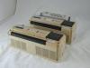
The PLC unit F2-40M has numbered inputs on one side and outputs on the other side. An input can be connected to various parts of the installation, including power, sensing and switching points. Outputs steer the powering of external points in the installation.
PLC programs can be entered or changed by using a programming panel device placed on top of the PLC. The programming panel has a display and a number of function and instruction keys. Besides manual programming it can read or write programs from or to a tape-cassette recorder. See for more the special notes.
PLC Programming Panel ...
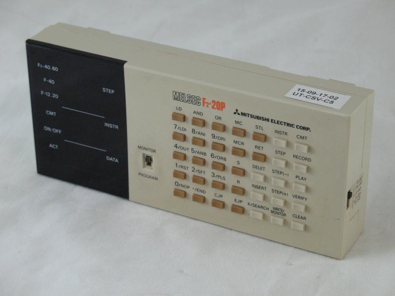
For programming the PLC a programming panel must be connected on top it. PLC's have a specific instruction repertoire. The instructions define logical steps by which the operation is controlled. The PLC program can consist of multiple, interacting control loops. Depending on input states, counters and timers, loops are cycled through. The Mitsubishi F2-series instructions consist of logical operations (LOAD/AND/OR/INVERSE) which may run in parallel (BLOCK-AND/OR). In addition, shift registers (SHIFT/RESET) can be programmed and specific functions activated (OUT/PULSE/NOP/END).
Using the panel, instructions can be entered or altered. The display on the panel shows instructions, program lines, timer- and counter-values. In this way, the operation of the PLC can be monitored and adjusted.
Graphical programming ...
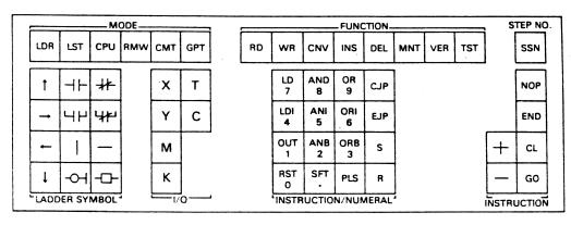
A graphic programming panel is provided for engineers familiar with graphical notations to represent switching logic. The graphical panel has different modes of programming the PLC. A frequently used mode is a symbolic notation based on so-called ladder diagrams (sometimes called “ladder logic”). These diagrams illustrates how electromechanical switches and relays are interconnected. See the photo with the layout of the panel keys.
More tools ...
A simulator unit is also available to simulate the operation of the PLC by manually applying signals to the contacts. In addition to control, a PLC can also collect process data. The graphics programmer from Mitsubishi offers the possibility to do this. A ROM cassette can be placed in the device, in which data is stored during a RUN. In that respect, the F2 PLC line of Mitsubishi offers the functionality of a so-called SCADA system (Supervisory Control and Data Acquisition).